


GRUPA WOLFF
Electrostatic discharges
Static electricity can be found practically everywhere. In everyday life, we perceive electrostatic discharges as painful but harmless nuisance. However, in the industrial environment, where flammable and explosive atmospheres occur, their effects can be devastating. Each year, numerous fires and explosions are caused by electrostatic discharges.
In order to understand how serious this threat is and to be able to control it in the right way, one needs to learn the principles of formation of electrostatic charges.
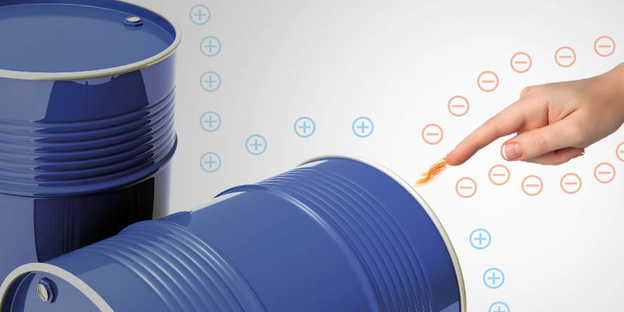
Every industrial process accompanied by movement, direct contact and separation of various types of materials leads to the phenomenon of electrization, i.e. accumulation of an excess of charges with the same polarity mark. Electrization can be caused e.g. by liquid flowing in a pipeline, powder sliding down a chute, a mixing process, and even by a person walking up and down a floor. When the electrized object has a good enough contact with the ground, the charge will be dispersed the moment it is generated. However, if the object is isolated from the ground by e.g. paint coating, laminate, rubber gaskets, or the soles of shoes, it will accumulate charges and its electrostatic potential and will grow. The moment when another subject of a lower potential occurs in its vicinity, an electrostatic discharge may come about – a phenomenon characterised by high voltage as able to ignite many types of atmospheres.
The processes most endangered with the an explosion resulting from an electrostatic discharge include:
- loading and unloading of road and rail tankers,
- filling and emptying of the various types of tanks, kegs and barrels,
- pouring of a liquid from one vessel into another, dosing and mixing.
The above industrial processes occur in virtually every production plant, therefore, it is essential that their users should be aware of the hazard and have knowledge on controlling the phenomenon of electrostatic discharges.
Table 1. Potential energy in the typical elements of installations. Source: UK IChemE.
Object | Capacity (pF) | Accumulated | Accumulated |
|---|---|---|---|
Road tanker | 5000 | 250 | 2250 |
Man | 200 | 10 | 90 |
Steel bucket | 20 | 1 | 9 |
Flange 100 mm | 10 | 0,5 | 4,5 |
Table 2. Minimum ignition energy (MIE) for vapours and dusts. Data source: UK IChemE.
Liquid vapour | MIE (mJ) | Powder cloud | MIE (mJ) |
|---|---|---|---|
Propanol | 0,65 | Wheat flour | 50 |
Ethyl acetate | 0,46 | Sugar | 30 |
Methane | 0,28 | Aluminium | 10 |
Hexane | 0,24 | Epoxy resin | 9 |
Methanol | 0,14 | Zirconium | 5 |
Carbon disulphide | 0,01 | Some pharmaceutical half-finished products | 1 |
Electrostatic earthing systems
Earthing of fixed elements of installations, such as piping, silos, pumps, etc., is a relatively easy and well recognized task. However, the situation becomes complicated in the case of the facilities which are not permanently linked with the installation. The facilities in questions include road and rail tankers, barrels, IBC containers or mobile vats of mixers. In such situations, it is necessary to use specially designed devices for a temporary connection and earthing of different types of facilities.
In practice, wires fitted with special clamps are applied for earthing mobile components of process installations. The free end of the wire is permanently attached to a verified earthing point (e.g. hoop-iron), while the clamp is fastened on the earthed object.
There are also solutions that are not only used for connecting and earthing of objects, but can also verify that the connection has been made properly and block the process when a negative response is obtain. This type of electronic systems is referred to as ground controllers.
Regardless of whether the grounding was done with the use a simple cable with a clamp, or a system with a controller, its resistance must not exceed 10 Ohms – this is a normative value.
Classification of earthing systems in respect of their characteristics
The table below presents the most important features of each type of the earthing systems offered by WOLFF GROUP.
Table 3. Characteristics and benefits for the user of various types of earthing systems.
Characteristic feature of the earthing system | Earth-Rite® | Bond-Rite® | Cen-Stat™ |
|---|---|---|---|
Volt-free contacts to control external devices, e.g. a pump, light or sound signalling | ✓ | ||
Continuous monitoring of the earthing connection status | ✓ | ✓ | |
Built-in light indicator that indicates to the operator (a red/green light) the current state of the earthing connection | ✓ | ✓ | |
Clamps with the ATEX/FM approval, with the sharp teeth of tungsten carbide as able to break through a layer of paint, laminate, pollution, etc. | ✓ | ✓ | ✓ |
Mechanically and chemically resistant cables protected with resistant Hytrel sheath | ✓ | ✓ | ✓ |