


Problem:
- High voltage transformers are subject to the risk of fire and explosion as a result of an electrical short circuit.
- Such events are sudden in their nature and thus the lack of a permanent fire suppression system may result in a total destruction of the transformer.
- This also poses a risk of fire spreading onto the remaining parts of the installation.
Solution:
- We have applied a fire detection system based on a sensor cable which detects the increase of temperature in thousands of locations within the transformer simultaneously.
- We have designed a fire protection sprinkler system in the form of self-supporting cages surrounding two transformers – the system ensures even coverage of the equipment with water mist.
![]()
Exemplary transformer sprinkler system
Objective: transformer fire protection
The objective was to build a fire detection and a sprinkler-based fire suppression system for oil transformers. The installation was designed to protect two 110 kV transformers. Additionally, the system had to be upgradable to cover a third transformer when needed.
The task was carried out for a chemical company as part of the construction of a transformer and distribution station.
Sprinkler system for transformers
A so-called cage, i.e. a spatial structure made of pipes equipped with 56 sprinklers was installed at each station. The sprinklers were positioned in such a manner as to make sure the transformer and its equipment is evenly covered with water mist. The cage is a self-supporting element and thus required no additional support structure.
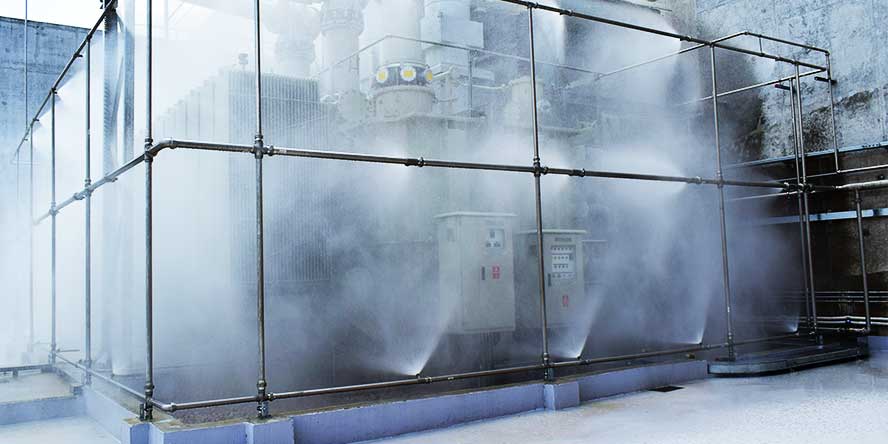
An exemplary test of a sprinkler system designed to protect a transformer against fire
With this approach, it was is not possible to connect pipes with quick couplings, which enable on-site cutting of pipes to fit and thus streamlines the work considerably. Instead, we used bolted flange joints which guarantee the required rigidity of the self-supporting cage. In this case, however, each element is prefabricated in advance. This means that high precision is required – if one of the elements does not fit the others, a new one must be made. This in turn could delay the works by up to several weeks. This is mainly due to the anti-corrosion technology used – more on that in the following sections.
All components used were certified and approved as required. They also met the investor’s specific requirements with regard to anti-corrosion protection. For example, the pipes used were hot-dip galvanized on both sides and then covered with special anti-corrosion coatings designed for use in harsh conditions typical of the chemical industry (resistant to, e.g. acid and lye vapours)..
The system features two actuator stations (flood valve stations), designed to ensure an immediate supply of fire extinguishing water to the sprinkler system. Diaphragm flood valves with national approvals as well as VdS and FM Global approvals were fitted.
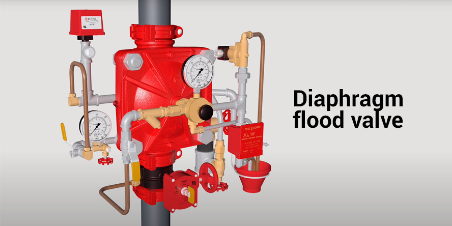 A diaphragm flood valve fitted in the transformer fire suppression system
The fire extinguishing procedure for the transformer was initiated in the following three ways:
- manual activation of the fire suppression system by means of a push button located in the control room,
- automatic activation of the fire suppression system by means of an electric signal from the transformer detection systems,
- manual opening of the flood valves.
Transformer fire detection
The fire detection system has two activation thresholds:
- transformer temperature increase above 80oC – detected with a special sensor cable,
- detection of anomalies in the cooling oil tank (short circuit, insulation breakdown, leakage) – a Buchholz relay installed in the transformer.
If any one of the above-mentioned events occurs, a sound alarm is activated and information about this fact is transmitted to the control room. At this point, the fire suppression system can be activated manually. If both tripping events occur simultaneously, the fire suppression system is activated automatically.
As mentioned above, a sensor cable was used for fire detection purposes. The sensor cable is maintenance-free and requires no special protection, therefore it is suitable for use in locations with no or limited access in the course of standard operation.
Testing and acceptance of the system
The works were completed with a system pressure test. For this purpose, a pressure of 0.8 MPa was maintained in the piping throughout 24 hours. The system pressure was examined after this time and its value was unchanged. Subsequently, the pressure was increased to 1.6 MPa for 30 min. This test was also passed successfully.
The pressure tests were followed by an operational test, which consisted in activation of the sprinkler system. This test was also passed successfully.
Assembly works and acceptance tests were performed in according to obligatory standards
Transformer fires and explosions
Fires and explosions of transformers are not uncommon. In February, the Polish Press Agency reported on a transformer fire at the Siekierki CHP Plant in Warsaw. The causes of the fire are yet to be determined. The following section also includes other examples from the previous year.
Preventive measures turned out to be insufficient in the Rybnik power plant
Prevention in the form of safety automation is an essential necessity. Unfortunately, as practice demonstrates, such solutions are not 100% effective. This was confirmed by the case of Rybnik power plant, where preventive safety devices worked properly, and yet there was a serious incident… an incident which was costly but more importantly which posed a direct threat to the the power unit.
This is how the incident was described by Bolesław Słowiński in the document entitled “Damaged high voltage insulating passage in a unit transformer causes a major breakdown in the power plant”:
An electrical short circuit resulted in an explosion in the transformer tank. As a result of the force of the explosion in the transformer, the welded upper cover of the tank was torn open, with the opening size of approx. 80 mm, along approx. 50% of its circumference. There was an ejection and leakage of transformer oil, which caught fire; subsequently, the fire engulfed the entire unit transformer.
The increase in the current up to the value of12.445 kA occurred in 2.8 ms, which, based on the rated current of the 8TB transformer, means that its value was: 33.5 x the rated current of the 8TB transformer. Such a rapid increase in the current value caused an immediate tripping of the differential protection and the associated electrical safety devices as well as disconnection of the circuit breakers for unit 8, unit 7 and the 400 kV power output lead. The current surge was caused by a single-phase electrical short-circuit of L2 phase of the 400 kV side to the earth caused by a damage to the insulating passage of the 8TB transformer.