


Zbigniew Wolff | z.wolff@grupa-wolff.eu | www.grupa-wolff.eu
Dedusting, central vacuum and aspiration systems are present in virtually every industrial plant. In many cases, dusts sucked into the system are explosive and, in some industries, explosive gases or vapours get to the installation along with dusts. How to cope in such cases with the maze of regulatory provisions applicable in the area of explosive safety?
The necessity of adequate protection of the plants endangered with explosions follows directly from the ATEX Directive 137 and the relevant Polish regulations. In practice, activities in this area are carried out on the basis of the relevant PN-EN and EN standards.
However, as efficient navigation in the maze of complex provisions is not an easy task, this article presents a practical approach to the problem of proper securing dust collection, central vacuum and aspiration systems against explosion effects.
Although the construction of the commonly used filtration units – at least in terms of basic assumptions – is more less the same, the approach to their proper protection against explosion can be radically different. The factors that chiefly determine this include:
-
- parameters of the dedusted explosive atmosphere,
- structural strength of the equipment, and
Explosive atmosphere
From the point of view of explosive safety, a key issue in the selection of the filter unit is the determination of parameters of the explosive atmosphere which may appear in the filter chamber and in dirty air channels, and in some cases also in the clean air channel.
The basic parameters which are necessary for proper design of an anti-explosive system include:
- Kst [bar x m/s] – the maximum increment of pressure in a given volume and unit time as caused by explosion of an explosive atmosphere,
- Pmax [bar] – the maximum pressure that can be achieved at the time of explosion of a particular explosive atmospheres in the filter unit (or other closed apparatus).
Filtration unit
To perform the necessary calculations, there are also indispensable the technical data of a particular filter unit which was chosen due to the required performance and quality of the purified air. The necessary minimum in this area includes:
- basic dimensions of the filter unit,
- number, type and size of filter cartridges,
- diameters and routes of dirty and clean air channels,
- structural strength of the device as expressed by the maximum pressure Pstat [bar] that the device is resistant to, i.e. it will not be broken (and in certain cases deformed) by that pressure.
Structural strength
The essential task of anti-explosive systems is reduction of the maximum explosion pressure Pmax to the value of the so called reduced explosion pressure Pred whose value in turn must be lower than the structural strength of the device Pstat. In other words, anti-explosion protections are to reduce the excessive increase of pressure inside the device after the explosion to a safe level, and thus to prevent its destruction (breaking) or serious damage (deformation).
Therefore, in the case of a properly secured plant, the following condition must be met:
Pred < Pstat < Pmax
Also note that the value of Pstat must be maintained also for the channels that connect the device with the rest of the plant. This condition applies to the channel segments on the length from the apparatus to the explosion decoupling (isolation) systems installed on those channels (decoupling systems protect against a breakthrough of explosion effects, including pressure and fire, to the remaining part of the plant).
The structural strength of the apparatus Pstat can be determined on the basis of two parameters, namely: the limit of elasticity or the yield point of the material that the device is made of. Both approaches are valid, but the use of the elastic limit ensures that the device will not be permanently deformed as a result of the explosion, and therefore, it will be fit for further operation. When the yield point is used for calculations, we only have the guarantee that the device will not be broken, but it can be subject to deformations that would eliminate it from further operation.
A higher structural strength generates a higher price of the unit. However, it follows from the experience that in many cases, the difference is relatively small.
It should be noted that calculation of the structural strength of Pstat is also possible in the case of devices operated for years and any activities in this field have recently gained in importance. This is because on the basis of the calculations and analyses carried out, it is possible to strengthen appropriately the devices, which allows to reduce the costs related to their possible replacement. An example of the establishment that has opted for this solution may be the Górażdże Cement Mill, where engineers of GRUPA WOLFF worked out an inventory of the alternative fuels grinding and dust removal plant and and then calculated the structural strength of individual devices.
Explosion protection
At present, there are four technical solutions on the market which in accordance with the ATEX directive 95 are approved under the Polish and European law for installation, among others, on filtration units. These are the explosion relief (venting) systems, flameless explosion venting systems, explosion suppression systems and structures withstanding the maximum explosion pressure. However, they serve only the purpose of protecting the apparatus against explosion effects. The main factor influencing the choice of protection is the location of the filtration unit (building/hall or open area) and the values of explosive atmosphere parameter.
Explosion relief
When deciding to install an explosion relief system, i.e. to discharge explosion effects (pressure, flame, burning particles and unburned product) outside the apparatus, to the atmosphere, one should be aware of a few key principles. It is necessary to determine the hazard zone, where the explosion wave will be directed to. This is necessary because it is generally forbidden to direct effects of an explosion toward buildings and other equipment and installations, pedestrian tracks and roads, parking lots, product storage areas, as well as towards areas where other explosive atmospheres may occur. This zone, the extent of which should be calculated, can be up to several tens of meters. Fencing of the zone is also recommended. These activities should be performed as part of the Explosion Risk Assessment.
Explosion relief with panels or anti-explosive dampers mounted on the side or top wall of the filtration unit as an executive element. For example, in the case of units with filter sleeves, the only feasible alternative is erection of the relief system on the side of the device, above the hopper, in such a way that the filtering sleeves do not cover the decompression hole. However, in the case of rectangular filter cartridges (plates or filter pockets) installation of decompression panels or flaps on the top part is only possible when the clean part of the filter is located on its side wall. As regards explosion relief systems, it should also be borne in mind that this type solutions are each time installed on the so called dirty side of the filter unit.
Most importantly, the anti-explosive panels and flaps are basically not applied in the case of devices located in indoor facilities. In the case of the former ones, a deviation from this rule is those few cases where it is allowed to use the so called decompression channels that enable derivation of explosion effects to an open space, outside the hall or the building. However, application of this solution has a number of technical limitations.
The use of a decompression channel in each case requires an individual approach. This is because as the length of the channel grows, there also grows the minimum required decompression area and/or the value of the reduced explosion pressure Pred. Also note that the decompression channel pressure should be conducted preferably at the right angle to the surface of the panel and its length as a rule should not exceed 3-4 metres. Other solutions are also possible, but they require additional, often complicated analyses and calculations.
Flameless Explosion Relief
In practice, in many cases, it turns out that the decompression channel so significantly affects the size of the required surface relief and/or the reduced explosion pressure that its application is physically impossible. Due to these reasons, application of standard decompression panels in closed rooms is very difficult and in many cases – just impossible.
An alternative solution is flameless explosion relief system. It is a combination of a decompression panel with perforated, efficient heat exchanger which constitutes a barrier to the flame and to the burning and unburned product, and at the same time allows to discharge the explosion pressure (exhaust gasses) to the environment.
Despite the many advantages of the flameless explosion relief, one should be aware of the fact that, as in the case of decompression panels, at the time of the explosion, excessive pressure and gases resulting from the combustion of the product are removed from the device to the surrounding atmosphere. Therefore, before choosing this solution, make sure that the ratio of the room volume to the volume of the protected device is compliant with the standard. In many cases, it can be assumed that this ratio should be not less than 1:15.
According to the ATEX Directive, explosion relief systems may not be used in those cases where the product or products of combustion are toxic or harmful to health (products of this type include, e.g. bone meal, dried sewage sludge, various chemical substances, etc.).
Explosion suppression
When, due to the above limitation, it is not possible to apply a relief system, an explosion suppression system comes to our aid. This is the most technically advanced solution for protection of the plant-floor devices against explosions. Its task, in contrast to the explosion relief, is to prevent the development of an explosion that is suppressed already at the source.
The system consists of detecting, controlling and actuating elements. The actuating elements are HRD (High Rate Discharge) type cylinders High filled with a special explosion suppressing powder. The filter unit is monitored by a sensor which continuously measures the change in pressure inside the device over time. In some cases, when shortening of the response time of the system is required, infrared sensors are additionally applied. The control unit is responsible for verification of signals from the sensors and the system activation.
In the case of systems based on a dynamic pressure sensor, activation of HRD cylinders occurs only when the change in pressure over time corresponds to the explosion characteristics of the particular product. Injection of suppressant inside the protected device does not allow for the explosion propagation through suppression of the forming flame, cooling of the product and inertisation of the system. Note that the suppression system is designed while taking into account individual requirements of a particular installation and limitations of the ATEX certification (systems from different manufacturers have different limitations). Depending on the product explosiveness characteristics and the volume of the protected device, the time measured from detection of the source of explosion to its complete suppression ranges from tens to hundreds of milliseconds.
The primary advantage of described system is the possibility of installation of a filter unit anywhere – in a building or a hall, on the roof, near pedestrian tracks or roads, within densely installed plants, etc. Construction of the HRD explosion suppression system eliminates the need for designating any danger zones. The HRD system is approved for use in the presence of the majority of dusts and gases.
A structure resistant to the maximum explosion pressure
In those rare cases where implementation of these solutions is not feasible, the only option left is to construct a filtration unit resistant to the maximum explosion pressure Pmax. The consequence of this solution is a large weight of the unit which in many cases makes it necessary to strengthen the ground or construction of the building on which the device is sited. It also means a major increase in costs.
Explosion decoupling (isolation)
Irrespective of the method used to protect the process apparatus (including filtration units) against explosions, it is necessary to supplement it with an explosion decoupling (isolation) system – which follows directly from the directive Atex 137. Application of explosion decoupling systems on filter unit input channels and, in some cases, on output ones and on the chute from the collected dust chamber, is intended to prevent the breakthrough of explosion effects (pressure) to other parts of the plant. So the primary role of explosion decoupling is to protect the process plant against transfer of the explosion from the endangered apparatus.
On the market, there are several solutions that are compatible with the directive ATEX 95, as well as with Polish and European regulations. Depending on the operational characteristics of the plant, routes of the channels and dust explosiveness parameters, it is possible to use e.g. cellular wheel sluices (cellular wheel valves, rotary sluices), special quench valves, back pressure flaps, double damper systems, fast acting valves, Ventex type valves and HRD type fire barriers.
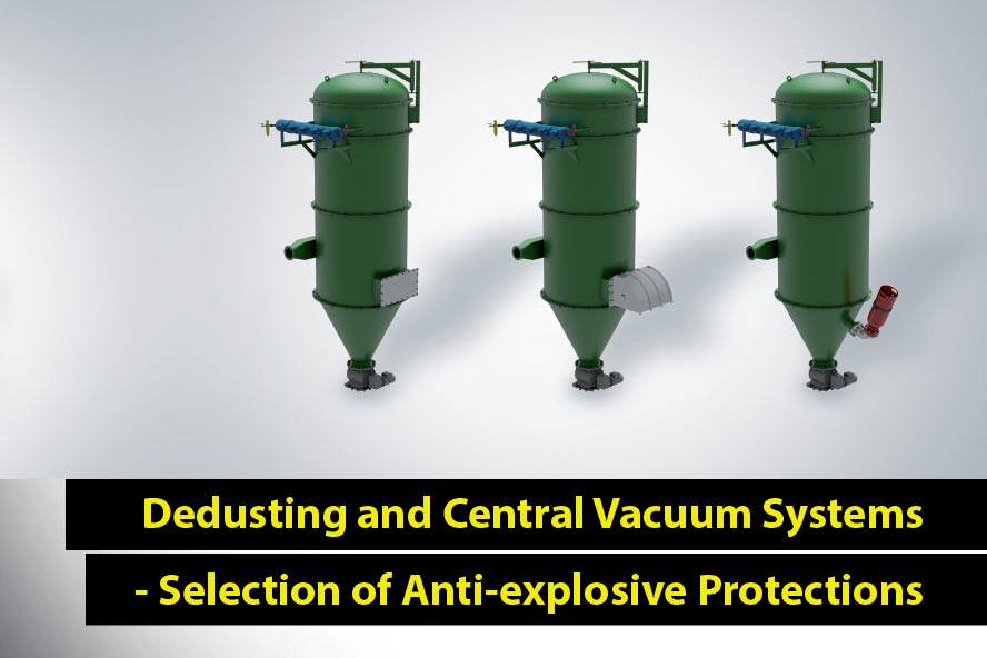
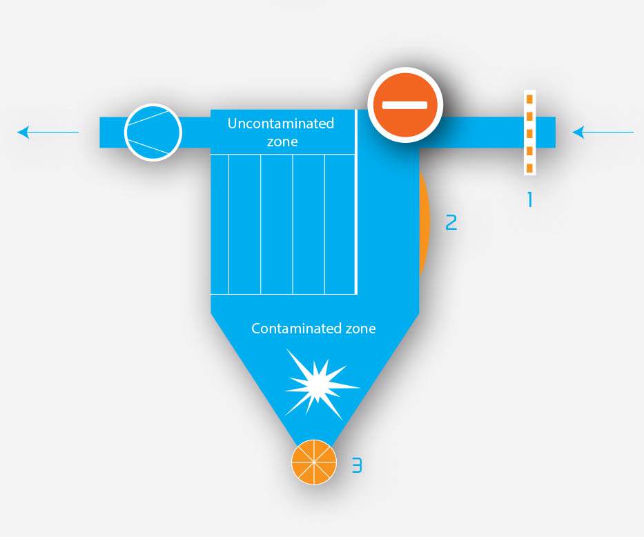
Protection of filters against explosions – an example of correct solutions
Filter protection: correct
Safety level: high
(1) A certified decoupling system has been applied on the dirty air channel (explosion suppression / back pressure flap), which in the case of explosion will effectively isolate the protected filter from the rest of the plant.
(2) Filtration cartridges have been raised in relation to the relief panel, which allows their proper activation in case of an explosion.
(3) A certified dosing valve has been applied at the outlet of the filter, which in case of explosion will separate effectively the protected device from the rest of the plant.
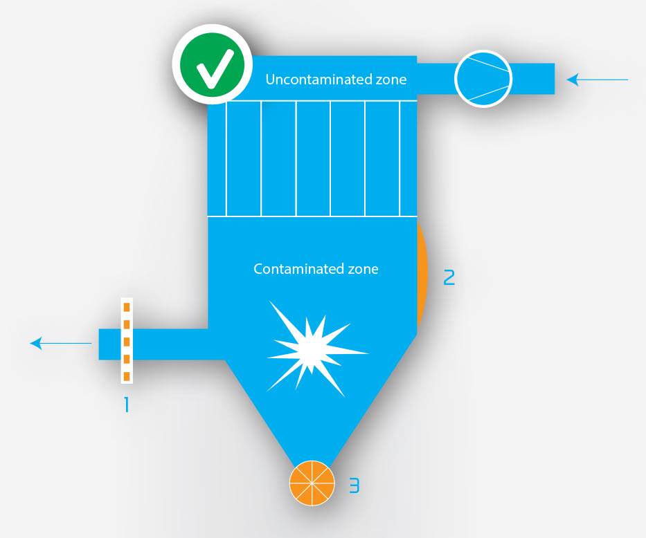
Filter protection: correct
Safety level: high
(1) A certified decoupling system has been applied on the dirty air channel (explosion suppression / back pressure flap).
(2) Explosion effects in the filter will be minimized to a safe level by the explosion suppression system.
(3) A certified dosing valve has been applied at the outlet of the conic section of the filter, which in case of explosion will separate effectively the protected device from the rest of the plant.
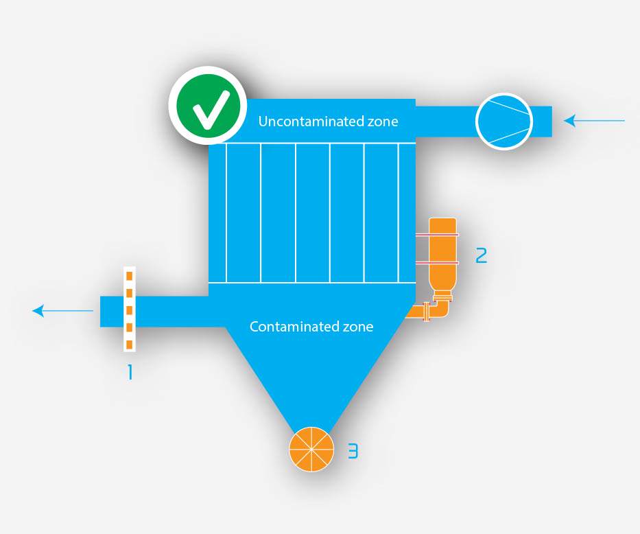
Protection of filters against explosions – an example of erroneous and acceptable solutions
Filter protection: incorrect
Safety level: inadmissible
(1) No explosion decoupling on the dirty air channel will allow the explosion to spread to the rest of the plant.
(2) Filtration cartridges mounted on the relief panel height will prevent effective discharge of explosion effects outside the protected device.
(3) At the outlet of the filter, a cellular wheel valve in the standard version has been applied (without an ATEX certificate confirming resistance to the pressure shock and fire breakthrough). This may result in the spread of the explosion to the rest of the plant.
Filter protection: correct
Safety level: admissible
(1) A certified decoupling system has been applied on the dirty air channel (HRD powder barrier / back pressure flap).
(2) Filter cartridges have been removed from the filter wall on which an explosion relief panel has been mounted. Particular attention should be paid to the dimensions of the channel thus formed. – In the case of an improper selection, the filter may require additional protective measures.
(3) A certified dosing valve has been applied at the outlet of the filter.