In one of the industrial plants, there was a massive explosion of aluminium dust, which led to catastrophic consequences. The above video presents a case study that shows step by step the causes and effects of the explosion. This event has also become the basis for this article on dust explosion hazards (particularly aluminium dust).
Aluminium dust explosion and fire at Hayes Lemmerz
If a dust explosion in a filter is a problem, then an aluminium dust explosion is a real challenge. This dust burns very rapidly, making it impossible for most explosion protection to work quickly enough, i.e., before the explosion pressure exceeds the protected apparatus’s design resistance. Fragmented aluminium reacts with water releasing explosive hydrogen, which, combined with the above arguments, also makes fire prevention significantly more difficult.
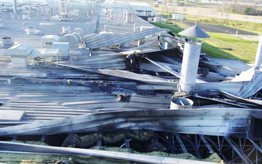
The first explosion took place in a dust filter located outside the hall. Then the pressure and flames spread through the dust pipe system to the other systems located inside the plant. There were further explosions, which caused the aluminium dust on the equipment, channels, and floors to rise into the air. A dust-air mixture was created, the ignition of which led to a powerful explosion. Its strength ripped a 15-meter-wide hole in the roof of the hall.

A 15-metre-long hole in the roof caused by a secondary aluminium dust explosion inside the hall.
Aluminium dust explosion parameters
As the table below shows, fragmented aluminium can have a very high maximum explosion pressure and an equally high explosibility factor Kst. These values indicate the high strength of the potential explosion, which, of course, will be extremely violent. These parameters constitute the biggest problem in the case of explosion suppression system selection, drastically reducing available opportunities. In most cases, the protections operate too slowly or do not have the appropriate certificate.
Additionally, fragmented aluminium has very low ignition energy (10-160 mJ), which means that even a small electrostatic spark can initiate the ignition. In turn, contact with water causes a reaction generating explosive hydrogen, which eliminates the possibility of extinguishing aluminium with water or foam.
All this means that we are dealing with a serious explosion and fire hazard against which it is hard to protect.
| ALUMINIUM DUST PARAMETERS | SAMPLE 1 | SAMPLE 2 | SAMPLE 3 |
|---|---|---|---|
| Particle size <71 μm [% weight] | 65 | 99 | 94 |
| Particle size <32 μm [% weight] | 47 | 64 | 60 |
| Particle size <20 μm [% weight] | 37 | 47 | 17 |
| Particle size — median [μm] | 36 | 22 | 29 |
| Lower explosion limit [g/m3] | 60 | 30 | 30 |
| Maximum explosion pressure [bar] | 12 | 11.5 | 12,4 |
| Explosibility factor KSt [bar m/s] | 750 | 1100 | 415 |
| Explosion class | St3 | St3 | St3 |
| Minimum ignition temperature of a dust cloud [°C] | 590 | 500 | 710 |
| Minimum ignition temperature of a dust layer [°C] | 450 | 450 | 450 |
NOTE: when the phrase “aluminium dust” or “ground aluminium” appears in this article, it is understood to mean aluminium in the form of powder, fine fibres or chips.
Hayes Lemmerz explosion prevention system
Although the parameters presented above have very high values, it should be stressed that all combustible dust poses an explosion hazard. For example, the Kst of aluminium dust taken from the Hayes Lemmerz plant was “only” 131 bar*m/sec. This means that it was possible to select a number of explosion protections in this particular plant that would ensure safety without major problems.
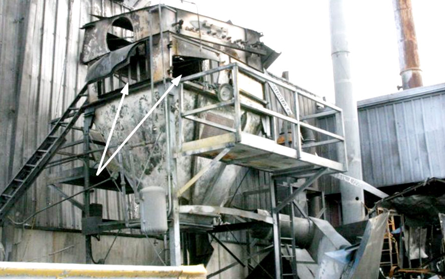
However, the incident report indicated that the devices were protected selectively, and the vent panels used did not have a proper decompression area. As a result, despite the security measures, the “protected” apparatuses burst. The dust collection system in which the first explosion occurred also did not have an explosion isolation system, which would have prevented the propagation of its effects through dust pipes to equipment located inside the hall.

The filter where the first explosion occurred. The arrows mark the decompression panel and the torn-out inspection door, which indicate that the area of the decompression panel was too small.
Ignition sources for aluminium dust
The above data indicate that aluminium can ignite, among other things, as a result of contact with a hot surface, electrostatic discharge, electric or mechanically generated spark, and also as a result of contact with hot particles, filings, or open fire. As aluminium dust belongs to the group of conductive dust (explosion subgroup IIIC), it can cause, e.g., short circuits, which are also a potential ignition source. A specific ignition source may also be the so-called thermite reaction, e.g., as a result of contact between aluminium and iron oxide contained in rust. Ignition could occur, e.g., when a rusty object hits the wall of a channel or an aluminium-coated device.
Protection against aluminium dust explosion
For the time being, the only certified protection that can legally be used to protect equipment against aluminium dust explosions are decompression panels in combination with an explosion-proof cut-off device resistant to its maximum pressure (e.g. quick-release gate valve or cell dispenser). Both types of protection, i.e., panels and explosion decoupling, are used in parallel, with each having a different function.
Why use decompression panels
The panels are a kind of safety valve, which is designed to release the explosion pressure and fire jet outside the protected apparatus. This allows the limiting of the pressure increase in the device above its design strength. However, for the panels to perform their function, they must have a minimum decompression area, which must be calculated. The following principle works here — the larger the decompression hole, the lower the required design resistance of the protected apparatus. Too small an opening may, therefore, not provide adequate ventilation and thus lead to uncontrolled bursting.
Limitations of decompression panels
Decompression panels are a simple, effective, and economical method of protecting installations from an explosion’s effects. However, this solution has a number of limitations, which make its application require experience and knowledge. The most important of these are discussed below.
Need to designate a hazard area
The decompression panels are the weakest design element of the protected apparatus, which is to “open” to release excessive pressure and fire jet to the environment at the moment of the explosion. According to the Dust explosion venting protective systems standard (PN-EN 14491-2012), this solution requires the designation of a hazard area. The field of impact, which must be calculated, can be from several to several tens of metres in length. This space must not contain other technological devices, buildings, people, pedestrian routes, etc.
Problems when used indoors
Panels can rarely be used to protect equipment located indoors. Although, in such cases, it is possible to use decompression channels, through which the pressure and fire are led to the outside of the building, in practice, their use is difficult.
This fact is based on the guidelines contained in the PN-EN 14491-2012 standard. These concern, among other things, the maximum length of the decompression channel, the influence of its length on the increase of the decompression area, or the maximum inclination of the channel in relation to the vertical line. In addition, in certain situations, the use of a decompression channel requires the structure of the protected apparatus to be reinforced.
In practice, the above limitations mean that the apparatus to be protected by a panel with a decompression channel must stand in the building wall’s immediate vicinity. As in the case of the panel itself, a hazard zone must be calculated and delimited at the duct’s outlet, where other technological equipment, buildings, people, pedestrian routes, etc. must not occur. Such a situation is not common.
On the other hand, the apparatus’s structural strength, the length of the decompression channel, and the minimum decompression area should be viewed as a triangle of dependence. – Changing one parameter affects the others.
For example, the elongation of the decompression channel increases the minimum decompression area or minimum structural strength of the apparatus. In other words, the effect of the channel elongation can be compensated for by increasing the minimum decompression area or by strengthening the structural resistance of the apparatus.
Another example is the silo. Using panels on its side reduces its capacity (decompression panels must never be covered with the product). Therefore, we may want to reduce their decompression area. This can be achieved by shortening the decompression channel (e.g., by changing the silo foundation) or by increasing the structural resistance of the silo by using appropriate silo reinforcements.
The force of rejection at the moment of the explosion
It is also essential that the panels’ installation considers the recoil force that arises at the moment of the explosion. To reduce it, the panels are installed on opposite sides of the apparatus, and when this cannot be utilised, calculations are made to show whether the explosion will not lead to the apparatus overturning. Sometimes it is necessary to make appropriate reinforcements to stabilise the protected device.
A fire as dangerous as an explosion
Unlike, e.g., explosion suppression systems, decompression panels do not eliminate the risk of fire that may occur after an explosion. This is particularly important in the case of aluminium dust, which burns extremely rapidly, both in the form of a cloud and a layer. Importantly, such fires must not be extinguished with water, which eliminates classic spray systems from use. For these reasons, extinguishing aluminium is an extremely difficult task, so it is very important to implement an effective detection system to respond to a fire’s early stages.
What to use if not decompression panels
These limitations make users look for other solutions. These exist on the market. Although they are proven in battle, unfortunately, they do not have the required aluminium dust certificates.
An example is the explosion suppression and decoupling system based on so-called HRD (High Rate Discharge) cylinders. We are familiar with using this solution to protect installations with an aluminium dust explosion hazard. Unfortunately, in such cases, full responsibility for the possible consequences of the explosion lies with the owner of the system.
Why use explosion decoupling
Several solutions can be used to decouple the aluminium explosion. Most often, however, it is either a quick-action gate or a cell dispenser.
The gate is used in channels and the dispenser at the outlet or less frequently at the inlet of the device. The role of these devices is to immediately cut off the apparatus in which the explosion occurred from the rest of the system. By applying this method, we prevent the fire from spreading to adjacent equipment and thus protect the system from the secondary explosion and extensive fire.
These devices have specific limitations, on which a separate article could be devoted. For now, we will only point out that the main disadvantage of the gate is its price. In addition, to be able to use it, the channel on which it is to be installed must have a certain minimum length, which is determined based on appropriate calculations.
However, in the case of the target dispenser, it should be stressed that it should be tested and certified for an explosion pressure higher than that of aluminium dust. In other words, the explosion decoupling function cannot be performed by every cell dispenser, but only by this with the corresponding ATEX certificate.


